Chenyi Wang
Sound Reactive LED
Physical Computing
2023.11 - 2023.12
This project is a simple sound reactive installation, which mainly uses two components, a sound sensor and an LED panel.
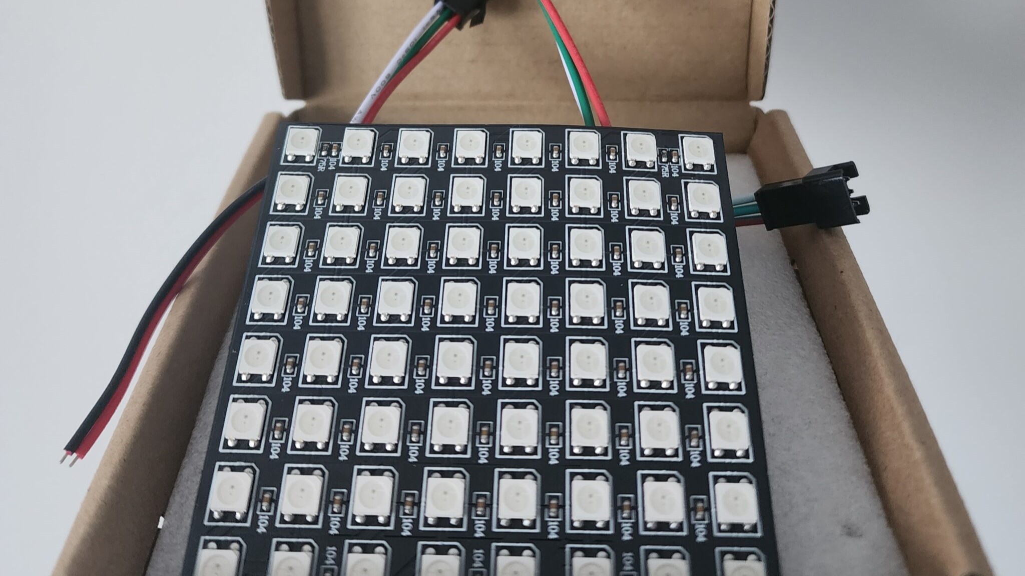
The sound sensor will detect the ambient sound and the LED panel will respond with a change in display. In my project, I used an 8×8 WS2812B LED Matrix panel. Both of the two components will be connected and controlled by Arduino.

The sound sensor only has three pins, VCC, ground, and signal pin. The part I bought has a built-in amplifier so I can use it directly without connecting extra components in the circuit. The sound sensor module also includes a potentiometer for adjusting the threshold of the sound level, which means I have to set the sensitivity of the output signal manually. I connected the sensor to the analog pin, and tested it: when the surroundings are quiet, the value of the sound sensor is 1023, and when the ambient sound is relatively loud, the value is around 75. These values can be later mapped to the display of the LED.
The connection of the LED panel is more complex as it cannot be connected to the Arduino directly. My LED panel has a size of 8×8, which has 64 LEDs, and each LED will need 20mA current to reach its full brightness, which means the Arduino can't handle the amount of current required for the entire panel, and an extra 5V power supply is needed. Other than the external power supply, the rest of the connection is similar to the sound sensor as it also only has three pins, VCC, ground, and digital input pin. The only difference is that I need to connect the VCC pin to the external power supply instead of the Arduino, and I need to ground the LED panel at both the Arduino and the external power supply.
To use the LED panel, I used a library called FastLED, which is a well-documented library for various LED components. After running a few sample codes and testing the basic functionality of the LED panel, I realized that it is a little harder to manipulate the display on the LED panel than I expected. Even though I can consider each LED as a pixel, the order of the LED is based on its circuit which is a zigzag. Therefore, I only implemented a simple effect of light change. I let the LED panel light up by rows based on the sound, that is, if the volume of the ambient sound is low, fewer rows of the LED panel will be turned on, and the louder the sound, the more rows of the LED will be turned on. Unfortunately, my LED panel only has eight rows, the overall effect would look better if I had a long LED strip, but it should be good enough to demonstrate what I have to try in this project.
Tools: Arduino, Sound Sensor, LED Matrix Panel